BRL Test is your stocking distributer for a line of game changing, powerful, handheld analyzers by Signal Hound.  Utilize the power and crisp display of your laptop or PC with these small USB connected spectrum analyzers, tracking generators and signal generators.  Out of this world software makes affordable yet powerful analysis available at a level the same or better as the big, traditional and costlier analyzers of before.

BRL Test proudly offers:

BB60C Real Time Spectrum Analyzer 6 GHz

USB-SA124B Spectrum Analyzer 12.4 GHz

USB-SA44B Spectrum Analyzer 4.4 GHz

USB-TG124A Tracking Generator 12.4 GHz

USB-TG44A Tracking Generator 4.4 GHz

VSG25A Signal Generator 2.5GHz

spike.jpg

Signal Hound BB60C 600.png

Call 407-682-4228 to get yours today at BRL Test.

By Matthew Burris

Components Expert


Parts fail and things break. It’s a fact of life and engineering. Some component failures can be avoided by good design practices, but many are out of the hands of designers. Identifying the offending component and why is might have failed is the first step to refining the design and increasing the reliability of a system that has been experiencing component failures.


How Components Fail

There are numerous reasons for why components fail.

Some failures are slow and graceful where there is time to identify the component and replace it before it fails completely and the equipment is down. Other failures are rapid, violent, and unexpected, all of which are tested for during product certification testing. Some of the most common reasons for components to fail include:

Over current

Over voltage

Over temperature

Connected incorrectly

Change in operating environment

Manufacturing defect

Mechanical shock

Mechanical stress

Radiation

Contamination

Packaging

Connections

Aging

Cascading failure

Corrosion

Rusting

Oxidizing

Thermal runaway

Loose connections

ElectroStatic Discharge (ESD)

Electrical stress

Bad circuit design


Component failures do follow a trend. In the early life of an electronic system, component failures are more common and the chance of failure drops as they are used. The reason for the drop in failure rates is that the components that have packaging, soldering, and manufacturing defects often fail within minutes or hours of first using the device. This is why many manufacturers include a several hour burn in period for their products.

This simple test eliminates the chance a bad component can slip through the manufacturing process and result in a broken device within hours of the end user first using it.

After the initial burn in period, component failures typically bottom out and happen randomly. As components are used or even just sit, they age.

Chemical reactions reduce the quality of the packaging, wires, and the component, and mechanical and thermal cycling take their toll on the mechanical strength of the component. These factors cause failure rates to continuously increase as a product ages. This is why failures are often classified by either their root cause or by when the failed in the life of the component.


Identifying a Failed Component

When a component fails there are a few indicators that can help identify the component that failed and aid in troubleshooting electronics. These indicators are:

Visible

-The most obvious indicator that a specific component has failed is through a visual inspection. Failed components often have burnt or melted areas, or have bulged out and expanded. Capacitors are often found bulged out, especially electrolytic capacitors around their metal tops. IC packages often have a small hole burned in them where the hot stop on the component vaporized the plastic around the hot spot all the way through the IC package.


Smell

– When components fail, a thermal overload often occurs which causes the magic blue smoke and other colorful smoke to be released by the offending component. The smoke also has a very distinct smell and varies by type of component. This is often the first sign of a component failure beyond the device not working. Often the distinct smell of a failed component will stay around the component for days or weeks which can aid in identifying the offending component during troubleshooting.


Sound

– Sometimes components make a sound when they fail. This happens more often with rapid thermal failures, over voltages, and over current events. When a component fails this violently, a smell often accompanies the failure. Hearing a component fail is rarer, and it often means that pieces of the component will be found loose in the product so identifying the component that failed may come down to finding which component is no longer on the PCB or in the system.


Testing

– Sometimes the only way to identify a component that has failed is to test individual components. This can be very challenging on a PCB since often other components will influence the measurement since all measurements involve applying a small voltage or current, the circuit will respond to it and readings can be thrown off. If a system uses several subassemblies, often replacing subassemblies is a great way to narrow down on where the issue with the system is located.


By Matthew Burris

Components Expert

My time in the Civil Advocacy Clinic began in August 2015. I’d done two judicial internships, but I had never interacted with a client before, much less handled a case on my own. I remember receivi…

Source: Getting a Head Start on Life as a Lawyer

Side note: Gidget “Gabby” Benitez was the original creator of this very blog AMP!  All of us at BRL Test are so very proud of our alumni Gabby!

BRL Test – We have the best prices on the best amplifiers.  BRL Test is your authorized Ophir RF distributer.

Click here for 5084 data sheet and online quotes now.  Standard unit priced at $5,500.  60 day ARO / lead time.

Th Ophir RF 5084 is a 25 watt linear power RF amplifier with 0.01 – 230 MHz frequency range.  It features excellent 3rd order intercept point, wide dynamic range and high gain.

Built to last and backed by a great company with a great 3 year warranty.  Manufacture’s calibration and certification.  We are commitment to complete customer satisfaction.

Call your BRL Test representative at 407-682-4228 today

Ophir RF 5084     BRL-TEST


8722ES10-12blu

BRL Test – We absolutely know Agilent signal generators.  We believe the 8722ES is a very relevant and affordable network analyzer.   We give it our Lifetime Support Promise.  We are here to see that your 8722ES has the parts and the technicians to keep it working and accurate for the next 10, 20 or even 30 years.  Thats our promise.  Never obsolete.

The BRL Test business model relies, in part,  on sales of premium quality used electronic test equipment at low prices with a great warranty that is fully backed by our world class repair lab.  Our expertise means we do warranty repairs fast.  Low acquisition costs and less downtime risk on relevant equipment.  Thats us.

spec sheet data sheet

Agilent 8722ES

Click here to get an online quote for the 8722ES

This network analyzer allows complete characterization of RF and microwave components. The Agilent 8722ES vector network analyzer includes an integrated synthesized source, test set and tuned receiver. The built-in S-parameter test set provides a full range of magnitude and phase measurements in both the forward and reverse directions. Built-in vector accuracy enhancement techniques include full two-port, adapter-removal, and optional TRL calibration.

  • 50 MHz to 40 GHz 100 dB of dynamic range
  • Excellent measurement accuracy
  • Two measurement channelsBRL-TEST
  • Four display channels
  • Frequency and power sweeps
  • Fast sweep and data transfer speed
  • Pass/Fail testing, powerful marker functions Electronic calibration (ECal)
  • Internal automation with test-sequencing
  • Optional time-domain, high power test set, four samplers and TRL calibration, direct sampler access, frequency-offset mode

Save on premium quality used 8722ES. Freshly calibrated, certified and guaranteed to work accurately right out of the box – no worries.
Purchase easy knowing that y
our full warranty is backed up by our in house repair engineering department . Our military trained techs repair 8722ES’s at our world class lab. We absolutely know Agilent network analyzers.

Options for 8722ES:
007 Mechanical Transfer Switch
010 Add time domain capability
012 Adds direct sampler access
050 Standard Test Set Configuration
085 High power test set: automatically includes mechanical transfer switch and direct sampler access
089 Frequency off-set mode for mixer measurement capability
0B0 No prog/service/user guide (no manuals at all)
0B1 Extra manual set, English
0BV Add Copy of Documentation,assembly level
0BW Service documentation,assembly level
1CM Rack mount kit for installation without handles
1CP Rack mount kit for installation with handles
1D5 High stability frequency reference
400 Adds fourth Sampler and TRL calibration firmware
701 Three Sampler Test Set
702 Standard solid state transfer switch
703 No sampler access
704 Standard configuration with no mixer measurement capability

Repair 8722es

(Also known as the Keysight 8722ES )


equipment photoLow prices on premium quality test equipment is what we are about.  Our world class repair lab is what sets us apart.
Click to shop spectrum analyzers, network analyzers, sig
nal, generators
, oscilloscopes, EMC,parametric testers,  communication testers, digital multimeters,BERT, AWG, sweeper generators and more at BRLTEST.com
BRL-TEST
Call 866-275-8378 before their gone
Click on links below for datasheets and quote forms

Anritsu 37269B/2 Vector Network Analyzer, 10 MHz to 40 GHz $19,500.00
Anritsu MA24106A USB Power Sensor 50 MHz- 6 GHz, -40 dBm to +23 dBm $1,500.00
Anritsu MA2472B Power Sensor, Diode, 10 MHz to 18 GHz, -70 to +20 dBm $790.00
Bode 100 Vector Network Analyzer 1KHz to 40 MHz New in Box $5,490.00
Boonton BTN 4532 RF Peak Power Meter, Dual Channel, 10 kHz to 40 GHz $3,490.00
Boonton Electronics BTN 51011-EMC 50 ohm Diode Power Sensor $1,900.00
California Instruments Model 351TC AC Power Source 45Hz -5kHz w/ 849TA $3,990.00
Com-Power AH-118 Double Ridge Waveguide Antenna 18GHz *New 2yr warranty* $2,830.00
Com-Power AB-900 Biconical Antenna 1-6 GHz *New, 2 yr warranty* $1,029.00
Com-Power ABM-6000 Microwave Biconical Antenna *New, 2 yr warranty* $1,850.00
Com-Power AH-640 Horn Antenna 40 GHz *New 2yr warranty* $1,275.00
Com-Power AL-130 Loop Antenna 30 MHz *New 2yr warranty* $2,375.00
Com-Power ALC-100 Com-Power Compact Log Periodic Antenna *New 2yr warranty* $1,250.00
Com-Power AM-741 Active Monopole Antenna 30 MHz *New 2yr warranty* $2,060.00
Com-Power CDN-M325E Powerline Coupling and Decoupling Network. New in box. $1,325.00
Com-Power CIS-50W pwr amp,CDN, D couplers, attenuators..Conducted Immmunity System $10,545.00
Com-Power LI-325 Line Impedance Stabilizer 10kHz-40MHz, New in box, 2yr warranty. $1,425.00
Elgar 5699959-01 DC Power Supply Module for AT8000 & AT8000A $2,990.00
Fluke 5700A High Performance Multifunction Calibrator, 17025 A2LA Cert by FLUKE $19,990.00
Fujikura FSM-50S ARC Fusion Splicer FSM50S $3,900.00
Gigatronics 80321A RF Power Sensor, CW, 10 MHz- 18 GHz, 5 W $675.00
Hameg HM8143 Arbitrary Power Supply Unit 130 w/ Opt: HO880 GPIB $990.00
KT-1131A InfiniiMax 3.5 GHz Probe w/ KT-E2875A Differential Browser $2,500.00
KT-1134A InfiniiMax 7GHz Probe $1,900.00
KT-1156A Active Probe 1.5GHz w/ Accessories and Case $1,500.00
KT-11713B Attenuator/Switch Driver •24V, single voltage•1.7 A maximum $1,400.00
KT-11974A Preselected Millimeter Mixer,26.5-40GHz w/ 11974-60028 Supply $1,750.00
KT-16196B Parallel Electrode SMD Test Fixture, DC to 3 GHz $1,990.00
KT-16702B Logic Analysis System w/ 1* 16717A Module $1,250.00
KT-33220A Function / Arbitrary Waveform Generator, 20 MHz $990.00
KT-4062UX Agilent Parametric Tester $49,900.00
KT-4073A Agilent Parametric Tester call
KT-53230A opts:106/150/201/400 Universal Frequency Counter/Timer, 350MHz $3,750.00
KT-5335A opts 010/020 Universal Counter, 200 MHz $450.00
KT-81104A Pulse / Pattern Generator with the 81105A 80 MHz Output Channel $2,990.00
KT-83651B Synthesized Source, 45 MHz to 50 GHz $14,900.00
KT-83751A/1EDSynthesized Sweeper, 2-20 GHz $5,900.00
KT-8508A Vector Voltmeter w/ Bail Handle Range, 100 kHz to 1 GHz $1,995.00
KT-85092A/00F RF Electronic Calibration (ECal) Module, Type-N $2,490.00
KT-85107B Network Analyzer System 50 GHz, 8510C 8517B 83651B $19,900.00
KT-8510SX Network Analyzer System 26.5GHz, 8510C/10 /8515A/83631B $14,900.00
KT-85131F Flexible Cable Set, 3.5 mm (Test Port) to 3.5 mm $1,900.00
KT-8515A S-Parameter Test Set 45 MHz to 26.5 GHz, 3.5mm $1,500.00
KT-8562B opt 001 Portable Spectrum Analyzer, 9 kHz to 22 GHz $5,900.00
KT-86112A 20 GHz Dual Channel Electrical Module for 86100A/B/C/D $2,900.00
KT-8753D/ 011 RF Network Analyzer, 300 kHz – 3 GHz $2,900.00
KT-8753ES S-parameter Network Analyzer, 30 kHz – 3 GHz $6,750.00
KT-DSO8104A w/ opt 40 Infiniium Oscilloscope: 1 GHz, 4GSa/s,4 channels $5,990.00
KT-E4406A /BAF/ VSA Transmitter Tester, 7 MHz – 4 GHz $1,500.00
KT-E4440A many opt mixes call Spectrum Analyzer, 3Hz-26.5GHz $16,900.00
KT-E4448A many option mixes (call) 3Hz-50GHz PSA Spectrum Analyzer call
KT-E8257D/520/1EA Analog Signal Generator, 250 kHz to 20 GHz, w/ Step Attenuator $24,900.00
KT-E9300H E-Series Average Power Sensor, 10 MHz -18 GHz, -30 dBm to +44 dBm $1,490.00
KT-E9300H E-Series Average Power Sensor, 10MHz-18GHz,-50dBm to +30dBm $950.00
KT-EPM-442A Power Meter Dual Channel (E4419A) w/ 2 Cables $2,000.00
KT-N4419A S-parameter Test Set, 45 MHz to 20 GHz $2,400.00
KT-N5181A-503 many option mixes (call) 100kHz-3GHz MXG Analog Signal Generator call
KT-N5181A-506 many option mixes (call) 100kHz-6GHz MXG Analog Signal Generator call
KT-N5183A-532 many option mixes (call) 100kHz-31.8GHz Signal Generator call
KT-N6700B Modular Power System Mainframe, 400W, w/ N6731B/N6754A/N6775A $5,400.00
KT-N9030A-526 many option mixes (call) 3Hz-26.5GHz PXA Signal Analyzer call
KT-N9030A-544 Call for opts3Hz-44.0GHz Signal Analyzer call
KT-N9330A/ F40 Handheld Cable and Antenna Tester 25 MHz – 4 GHz $3,500.00
KT-N9340A Handheld RF Spectrum Analyzer,100kHz-3GHz $2,800.00
KT-U2761A USB Modular Function/ Arbitrary Waveform Generator $1,100.00
LeCroy Teledyne WaveRunner LT364 4-Ch,500MHz,1GS/s,1000MS/s, 2Mpts/Ch Color DSO $1,499.00
LeCroy Wavemaster 8600A 6GHz, 4CH,20 GSa/s $8,990.00
LeCroy WavePro 7300 3GHz, 4 CH, Digital Oscilloscope $5,900.00
LeCroy WaveRunner 104XI /VL/JTA2/UART/XWAV 1GHz, 4Ch $5,990.00
LeCroy WaveRunner LT364 4-Ch,500MHz,1GS/s,1000MS/s, 2Mpts/4Ch DSO $1,499.00
NoiseCom UFX-PNG7110 Programmable Noise Generator 10MHz – 1.5GHz $2,900.00
Ophir RF Linear Power RF Amplifiers for EMC All Freq Ranges and Outputs call
Ophir RF 5022A Linear Power RF Amplifier EMC, 800MHz-2GHz, 50W, New, 3yr warr $6,900.00
Ophir RF 5265 Linear Power RF Amplifier for EMC 0.7-4.2 GHz, 200W, New, 3yr warr. $48,900.00
Ophir RF 5293 Linear Power RF Amplifier for EMC, 1-6GHz, 50W, New, 3yr warr. $19,370.00
Picotest J2100 Injection Transformer. New in Box $525.00
Protek A434L Analyzer 5MHz-4GHz, VSWR, DTF, Cable Loss, Pwr, New $4,650.00
Protek A734 Spectrum Analyzer Handheld 4.4GHz, Sunlight Readable, Zero Span, New $4,650.00
Quadtech Guardian 1050 Ground Bond Tester $1,990.00
RS-FSEA30/B4/B7 Spectrum Analyzer 20 Hz – 3.5 GHz $4,900.00
RS-FSH4.04/K40 Handeld Spectrum Analyzer 3.6 GHz $2,490.00
RS-ESU40 20Hz-40GHz EMI Test Receiver call $123,098.75
RS-FSEB30/ B4/B7 Spectrum Analyzer 20Hz – 7GHz $3,490.00
RS-FSEM20 Spectrum Analyzer 9Hz – 26.5GHz, w/ opt. B1 = Color $7,000.00
RS-FSH-Z1 Power Sensor, 10MHz-8GHz, 200pW – 200mW 1155.4505.02 $1,250.00
RS-FSH3.23 Analyzer opt: B1/K1/K2, 100kHz-3GHz $3,900.00
RS-FSH4.04 Handeld Spectrum Analyzer 3.6 GHz opt: K40 $2,400.00
RS-FSP7 opt B16 Spectrum Analyzer, 9 KHz to 7 GHz $5,900.00
RS-FSU67/call opts 20Hz-67GHz Spectrum Analyzer $94,798.75
RS-SMF100A-call for opts 1GHz-22GHz Signal Generator $34,786.25
TEK-AFG3011 Arbitrary/Function Generator, 20 VPP, 1 CHANNEL $1,499.00
TEK-CSA8000 Communications Signal Analyzer 12.5GHz $3,900.00
TEK-DSA70804C: 8GHz 4CH Digital Serial Analyzer $74,937.50
TEK-DSA72004C/ call opts 20GHz 4CH Digital Serial Analyzer $162,437.50
TEK-DSA72504D: 25GHz 4CH Serial Analyzer Digital $137,500.00
TEK-DSA73304D: 33GHz 4CH Serial Analyzer Digital $186,250.00
TEK-MSO71254C call opts Mixed Signal Oscilloscope $168,750.00
TEK-RTD710A 1R Analog Waveform Digitizer 100 MHz $3,900.00
TEK-TDS3054 Digital Oscilloscope 500 MHz, 5 GS/s, VGA Color LCD 4 Channel $3,400.00
TEK-TEK P7516 TekConnect TriMode™ Differential Probe 16 GHz 067-1821-00 $5,900.00

85131F

3.5 mm Flexible Test Port Return Cables – Agilent 85131F On Sale at BRL Test $1,900

Click here for data sheets and 85131F quote forms at BRL Test   Call your BRL Test representative at 407-682-4228

BRL-TEST

| Microwaves and RF

Today’s satcom market can be analyzed by examining five focal points: Ka-band products, GaN devices, solid-state power amplifiers (SSPAs), traveling-wave-tube amplifiers (TWTAs), and passive components.

The latest RF/microwave technology is enhancing performance for the satellite-communications (satcom) industry with a wide range of products. Among the products leading this charge are high-power gallium-nitride (GaN) devices, which are empowering the next generation of solid-state power amplifiers (SSPAs). Because GaN technology can achieve performance levels beyond previous-generation technology, SSPA manufacturers can develop their products with better performance in smaller sizes.

While GaN technology has certainly received a significant amount of attention, traveling-wave-tube (TWT) technology remains a vital aspect of the satcom industry. Ka-band is another major focus, as the usage of this frequency band has significantly increased in recent years. Many Ka-band products are on the market today, as manufacturers seek to support this frequency band. In addition, manufacturers of passive components are supporting the satcom industry with a wide range of products intended for satcom applications. By taking a closer look at these five areas, it is possible to track the near-term evolution of satcom and discover how RF/microwave technology is enabling the satcom industry.

1. Ka-Band Communications

Ka-band is the most recently utilized frequency band to be authorized for commercial satcom. In comparison to other satcom bands, such as Ku-band, Ka-band uses bandwidth more efficiently and is less congested. Thus, Ka-band has become a popular choice for satellite operators in recent years. Although there are some differences worldwide in regards to its exact frequency range, Ka-band is generally considered to span 17.3 to 31.0 GHz. A vast array of RF/microwave products intended for Ka-band satcom applications is available today.

Fig. 1

1. This MMIC amplifier provides 40 W saturated output power from 13.75 to 14.50 GHz. (Courtesy of Cree)

Typical block upconverters (BUCs) used in satellite uplink transmissions convert a band of signals from the L-band frequency range to a higher frequency band, such as C-, Ku-, and Ka-band. The block downconverters (BDCs) that are typically used in satellite downlink transmissions perform the reverse function. They convert a band of signals from a frequency range, such as C-, Ku-, and Ka-band, down to the lower L-band frequency range.

With Ka-band communications becoming more prevalent, high-performance Ka-band BUCs and BDCs are needed to support these requirements. Among the companies offering Ka-band BUCs and BDCs are L3 Narda-MITEQ, GeoSync Microwave, Cross Technologies, Jersey Microwave, and WORK Microwave, to name a few. Some suppliers offer the option to purchase these BUCs/BDCs as either an outdoor unit intended for antenna-mounting or as an indoor unit intended for rack-mounting.

2. High-Power GaN Devices

Today, high-power GaN devices are being used to create the next-generation of GaN-based SSPAs. Prior to the advent of GaN technology, high-power gallium-arsenide (GaAs) devices were widely used to design SSPAs. Thanks to GaN technology’s continuous improvements, SSPA manufacturers are now building SSPAs with GaN devices. GaN technology offers a number of performance benefits in comparison to the older GaAs technology. A GaN device can deliver significantly more power density than a GaAs device. Thus, GaN-based SSPAs can be designed by power-combining fewer devices, resulting in greater efficiency. This also enables GaN-based SSPAs to be built in smaller package sizes than GaAs-based SSPAs. New high-power GaN devices have recently been released, providing additional high-power solutions to the satcom market.

With its portfolio of high-power GaN devices, Cree is one company enabling GaN technology to be utilized in satcom applications. The company recently added to its product line with the release of a new high-power monolithic microwave integrated circuit (MMIC) (Fig. 1). This GaN MMIC is a two-stage high-power amplifier (HPA) intended for Ku-band applications. It is available in a 10-lead, 25-×-9.9-mm, metal/ceramic flanged package (model CMPA1D1E025F) or as bare die (model CMPA1D1E030D).

“Cree’s new Ku-band GaN MMIC HPA was specifically designed in response to customer requests for higher-power and higher-efficiency Ku-band amplifier solutions,” said Tom Dekker, director of sales and marketing, Cree RF. “By delivering higher power, gain, and efficiency at an affordable price point, this amplifier will set the new standard for Ku-band performance.”

Dekker added, “Covering the 13.50-to-14.75-GHz commercial satcom band, the 30-W gallium-nitride-on-silicon-carbide (GaN-on-SiC) MMIC, two-stage high-power amplifier (HPA) enables the satcom industry to achieve higher-power and more efficient Ku-band solutions than the incumbent traveling-wave-tube (TWT) or GaAs solutions used currently. Applications include unmanned intelligence, surveillance, and reconnaissance (ISR), satcom-on-the-move (SOTM) ground vehicles, manned and unmanned aircraft, and maritime vessels.”

High-power GaN devices from Cree are also available for other satcom bands. An example is model CGHV96050F1, which is intended for X-band applications. Ka-band products are also currently being developed.

Fig. 2

2. These SSPAs will soon be available for both Ku- and Ka-band, providing output power levels to 100 W and 50 W, respectively. (Courtesy of Mission Microwave Technologies)

In addition, Qorvo recently released GaN power amplifiers (PAs) intended for commercial very-small-aperture-terminal (VSAT) and military satcom applications. Those PAs include the TGA2239-CP, TGA2595-CP, and TGA2594-HM. The TGA2239-CP is intended for Ku-band applications, while the TGA2595-CP and TGA2594-HM both target Ka-band applications. The TGA2239-CP provides 35 W output power from 13.4 to 15.5 GHz. The TGA-2595-CP is an 8-W PA covering 27.5 to 31.0 GHz, while the TGA2594-HM provides +36.5 dBm of output power from 27 to 31 GHz. These PAs add to the company’s existing portfolio of high-power GaN products.

For its part, Toshiba has a line of high-power GaN devices that are suitable for C-, X-, and Ku- band applications. A new Ka-band, high-power GaN MMIC is also scheduled to be released by the end of this year. This MMIC, the TGM2931-15, will provide 15 W output power from 29 to 31 GHz. The company also recently began production of the TGI5867-130LH, which is a C-band, 130-W GaN device.

3. Solid-State Power Amplifiers

With the number of high-power GaN devices available on the market, SSPA manufacturers can design their products using the latest GaN technology. Advantech Wireless, for example, has an extensive product line of GaN-based SSPAs. The company offers GaN-based products for C-, X-, DBS-, and Ku-band. As part of the company’s SapphireBlu series, C- and X-band SSPAs with output power levels as high as 6.6 kW are available as well as Ku-band SSPAs with output power levels as high as 3 kW.

One newcomer to the scene is Mission Microwave Technologies. Founded in 2014, the company offers SSPAs with integrated BUCs in a cylindrical package (Fig. 2). The company utilizes advanced GaN transistors, power-combining technology, and novel full-system designs to create compact SSPAs.

“The amplifiers in the new Javelin and Stinger product lines deliver more than 100 W and 55 W at Ku-band, respectively,” said Francis Auricchio, Mission Microwave Technologies’ president and CEO. “Unmatched prime power efficiencies of over 20% are achieved in lightweight, compact form factors that include upconverters, linearization, and integrated power supplies. Both the Stinger and the Javelin amplifiers include a standard user-friendly Bluetooth mobile app remote for monitor-and-control, which makes it simple for users to adjust power levels on the fly without a physical connection to the amplifier. Ruggedized for harsh outdoor environments, our Ku-band amplifiers are available now, with 50-W and 25-W Ka-band amplifiers following right behind.”

Explaining the innovative packaging of these SSPAs, Auricchio noted, “Our unique packaging was developed as we worked to realize the absolute minimum in amplifier size, weight, and volume, which is difficult to achieve by more traditional methods without sacrificing performance and reliability. Typical rectangular-shaped units tend to have heatsinking across the amplifier that is either uniform and underutilized or inefficient and unbalanced. Our cylindrical package optimizes the heatsinking to where it is needed most and provides airflow over the complete amplifier body. These aspects together maintain thermal performance—even in a small form factor. Satcom customers continue to request smaller and lighter units, especially for mobile and man portable applications. By optimizing the form factor of our products, we have been able to deliver this without sacrificing performance.”

A wide range of GaN-based SSPAs also is offered by Teledyne Paradise Datacom. Outdoor SSPAs are available for S-, C-, X-, and Ku-band with a wide range of output power levels. The company provides various packaging options for these SSPAs.

The Outdoor PowerMAX, Teledyne Paradise Datacom’s new high-power SSPA system, was recently unveiled. Its system architecture is a multi-module amplifier system, which allows PowerMAX systems to be configured with a large variety of output power levels. It also is a scalable amplifier system, as an Outdoor PowerMAX system may be initially configured with four modules and later upgraded to eight modules in the field. In addition, the system can grow with future power and bandwidth demands. The C- and X-band versions of the Outdoor PowerMAX system can generate an output power level as high as 10 kW, while the Ku-band version provides as much as 5.7 kW output power.

4. Traveling-Wave-Tube Amplifiers

With the excitement created by GaN technology, it may seem like traveling-wave-tube amplifiers (TWTAs) have been abandoned. However, TWTAs are still being used today. In fact, the technology has advanced in recent years. TWTA manufacturers continue to release new products, demonstrating that this technology is alive and well.

Yet the debate between SSPAs and TWTAs continues. Manufacturers of SSPAs like to point out the advantages that SSPAs have over TWTAs. The introduction of GaN technology has added fuel to the fire, as GaN-based SSPAs can provide performance improvements over previous-generation GaAs-based SSPAs. While SSPAs do have their benefits, TWTAs can still provide advantages over SSPAs in some applications. Thus, deciding on a preferred amplifier technology is dependent on the specific application.

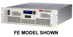
One company providing TWTAs to the satcom market is Tango Wave. The company offers TWTAs for DBS-, Ku-, and Ka-band with output power levels as high as 1250 W (Fig. 3). Those products are designed for direct-to-home (DTH), global up-linking, satellite news gathering (DSNG/SNG), broadcasting, voice/data, mobile up-linking, and maritime applications.

Fig. 3

3. Ku-, DBS-, and Ka-band TWTAs are now boasting output power levels as high as 1250 W. (Courtesy of Tango Wave)

For its part, Comtech Xicom Technology recently introduced the Ku- and DBS-band SuperPower Series TWTAs. These TWTAs are available in both frequency bands as either outdoor antenna-mount units or as indoor rack-mount units. The XTD-2000KHE model is a Ku-band TWTA that provides 750 W of linear output power while drawing less than 3200 W of prime power. The XTD-1500DBSHE model is a DBS-band TWTA that provides 560 W of linear power while drawing only 2500 W of prime power.

The SuperLinear TWTA product line from Communications & Power Industries (CPI) touts advantages in efficiency. These TWTAs range in efficiency from 13% for lower power models to over 22% for 2500-W amplifiers. The company offers SuperLinear TWTAs for X-, Ku-, and Ka-band.

LifeExtender is CPI’s new, patented technology, which is intended to increase a TWT’s lifespan. With the LifeExtender method, a TWT’s lifespan is extended by preserving the active coating on the cathode surface. A TWT reaches the end of its life when its cathode barium reserve is exhausted. The rate of barium evaporation is determined by the cathode temperature, which is in turn determined by the cathode heater voltage setting. With LifeExtender, the cathode heater voltage is adjusted over time to minimize the rate of barium depletion, thereby maximizing the life of the cathode. As a result, a TWT’s lifespan can increase by 30% to 50%.

5. Passive Components

Passive components are an integral part of any satcom system. These components include filters, couplers, isolators, and more. Many manufacturers offer a wide range of passive components for satcom applications.

For example, Advanced Technical Materials (ATM) offers an entire product line of components for Ka-band applications. These components cover the uplink frequency range of 27.5 to 31.0 GHz and the downlink frequency range of 18.3 to 20.2 GHz. The company offers both coaxial and waveguide models. The product line includes power dividers, attenuators, phase shifters, couplers, and more.

Another example of a company providing passive components to the satcom market is ETG Canada. The company’s SSPA original equipment manufacturer (OEM) product line is intended to allow SSPA OEMs to purchase waveguide components from the same vendor. This product line includes adapters, circulators/isolators, terminations, and couplers. The company’s TUBE HPA OEM product line includes many similar components intended for TWTA and klystron power amplifier (KPA) OEMs.

To summarize, a significant amount of activity is occurring in the RF/microwave industry in support of satcom applications. GaN technology is receiving a significant amount of attention, as it is enabling the next-generation of SSPAs. New high-power GaN devices will continue to be released in the near future. TWT technology also continues to be an important contributor to the satcom industry. And as Ka-band satellites continue to be implemented, suppliers are providing components to support this frequency band.

Download this article in .PDF format
This file type includes high resolution graphics and schematics when applicable.

BRL Test – We Absolutely Know Analyzers.  Click here for 8903B quote form and data sheet at BRLTest.com.

BRL Test has Agilent / HP 8903B Audio Analyzer Sale Priced at $999

BRL Test has Agilent / HP 8903B Audio Analyzer Sale Priced at $999

BRL-TESTAgilent 8903B Audio Analyzer
The Keysight/ Agilent/ HP 8903B audio analyzer. Ideally suited for audio measurements from 20 Hz to 100 kHz. The 8903B is an easy to use low-distortion audio source , high-performance distortion analyzer, frequency counter, ac voltmeter, dc voltmeter, and SINAD meter. With microprocessor control of source and analyzer, the 8903B can perform stimulus-response measurements (such as signal-to-spec sheet data sheetnoise ratio and swept distortion) automatically with no additional equipment. For ease of use, most measurements on the 8903B are made with only one or two keystrokes. The 8903B automatically tunes and auto ranges for maximum accuracy and resolution. For quick identification of input signals, the analyzer counts and displays the input frequency in all ac measurement modes.

Signal-to-Noise

Frequency Range: 50 Hz to 100 kHz

Display Range: 0 to 99.99 dB Accuracy: ±1 dB

Input Voltage Range: 50 mV to 300 V

Residual Noise (the higher of): 80 kHz BW: −85 dB or 17 µV 500 kHz BW: −70 dB or 50 µV

Supplemental Characteristics

Time to Return First Measurement: <2.5 second

Measurement Rate: One reading per second

Frequency

Range: 20 Hz to 100 kHz

Resolution: 0.3%

Accuracy: 0.3% of setting

Output Level

Range: 0.6 mV to 6 V open circuit

Resolution: 0.3% or better

Accuracy: 2% of setting 60 mV to 6 V, 20 Hz to 50 kHz. 3% of setting 6 mV to 6 V, 20 Hz to 100 kHz. 5% of setting 0.6 mV to 6 mV, 20 kHz to 100 kHz.

Flatness (1 kHz reference): ±0.7% (±0.06 dB), 20 Hz to 20 kHz. ±2.5% (±0.22 dB), 20 Hz to 100 kHz.

Distortion and Noise (the higher of): 80 kHz BW: −80 dB or 15 µV, 20 Hz to 20 kHz. 500 kHz BW: −70 dB or 38 µV, 20 Hz to 50 kHz. −65 dB or 38 µV, 50 kHz to 100 kHz.

Impedance: 600 Ω ±1% or 50 Ω ±2% front panel or HP-IB programmable (47 special function).

Frequency Switching Speed: ❤ ms (does not include HP-IB programming time)

Output Level Switching Speed: 20 ms (does not include HP-IB programming time)

Sweep Mode: Log sweep with up to 500 points per decade or 255 points total between entered start and stop frequencies.

Call your BRL Test representative today to lock in on this limited time pricing and availability 407-682-4228

Abstract: Wireless device range can be the pivotal make or break characteristic of a successful end product.  This paper will dig into the mystery and explore the mechanisms by which wireless range can be reduced or optimized through RF and antenna design. The discussion is relevant to board and system- level circuit and antenna design. The useful rule of thumb that every 1dB of additional RF loss reduces wireless range by 10% is presented.

Index Terms— Wi-Fi, Bluetooth, BLE, Zigbee, RFID, GSM, GPS, MBAN, HBAN, UWB, CDMA, Chip Antenna, Circuit Board Antenna, Wireless Range Reduction, Wireless Range Optimization, Radio Module, 802.11 and  802.15.4

Introduction

Any RF engineer who has optimized RF or microwave system hardware in the lab will agree that squeezing out the last 1 or 2dB from a design can be the most challenging aspect. After reading this paper you may better appreciate the value of such rigor. This is where the rubber meets the road for applying the art and science of RF design to the development of wireless products. At this point the product requirements may be defined, the theoretical path loss calculations may be complete and you want to ensure execution of the hardware development goes smoothly. Or, the product may be designed and prototypes delivered and debugged, but questions are being asked regarding the wireless range or lack thereof. This article will help the reader understand quantitatively how much wireless range may be lost if the antenna tuning and match steps are neglected, there is more RF loss in the design than anticipated or a related aspect of the design is out of control.

Unintended Loss in the Design

There are many possible sources of insertion loss, mismatch loss and general degradation of antenna gain.  These are RF signal losses resulting from product design decisions and features.  Collectively we will refer to these as unintended losses and all can have identical impact, which is to reduce the range of wireless products. By referring to them as unintended losses, we mean that they are a consequence of poor RF layout or antenna design and were not factored into the link budget calculation, which can be used early in the design to predict the range of a wireless device.

The RF engineer can prevent these problems and their disastrous consequences by optimizing the performance critical aspects of the design before the prototypes are built, and continuing the optimization and performance assessment in the lab when the hardware is available. This is not a long and drawn out process. It is a matter of simply involving the right expertise with access to the proper design, simulation, and test and measurement tools at the right times.  The end result will be a product which provides the best possible wireless performance for your customers and shareholders, with predictable cost and schedule.

Common Sources of Unintended Loss

The contributions from all sources of unintended loss are cumulative, including the separate losses of each of the 2 radios participating in a wireless link. For example, if we have 2dB of mismatch loss and the antenna gain is degraded by 2dB due to the layout, the impact of 4dB must be considered.  If two such identical radios are communicating, then the total impact of 8dB must be considered.

Antenna Match

Antenna match refers to optimizing the impedance matching network classically located close to the antenna using a piece of test equipment called a RF Vector Network Analyser. The impedance matching network is typically composed of lumped element capacitors and/or inductors, which has values that must be chosen or transmission line stubs which must be trimmed. Once the impedance matching network is tuned based on precision laboratory measurement, subsequent product may be built using the values determined. The purpose of matching the antenna is to force it to resonate over the appropriate range of frequencies for the radio, and to couple as much energy as is possible between the 50 ohm antenna and transmit/receive circuitry.

Circuit Board Layout

If the antenna is mounted on or integrated into a circuit board, careful attention must be given to the layout and the Gerber files reviewed. Often times the antenna used is really only half of the antenna capability since the circuit board RF ground plane plays a key role in the antenna performance. Without the presence of the ground plane and proper control and checking of all the geometric positioning of the antenna and the matching and feed network, the design may be destined to provide poor wireless performance before it is fabricated. The board layout team must be given detailed guidance and instruction, including the positioning of vias critical to RF performance. Simulation tools as well as theoretical knowledge as to how signals behave on circuit boards are needed to get this part of the design right.

Integration of Antenna into Operating Environment

Your end product may use more than one circuit board or contain other large conductive objects such as shielded LAN or USB connectors, transformers or discrete wires and cables.  All of these can profoundly impact the performance of your antenna as can proximity to materials such as plastics and conductors. The typical use case should be evaluated, including accessories. Proximity to the human body must be considered if the device is handheld or body worn.  Integration of the antenna into the product enclosure refers to evaluating the entire product design with respect to the antenna(s), retuning the impedance matching network in the final assembled product since everything mentioned above can impact antenna performance. Tuning the board used for laboratory development is often different from the final product tuning!

Quantify Impact of Loss on Wireless Range

Free Space Path Loss

Once prototype hardware is built and the wireless link functioning in the lab, the easiest part of the link budget to modify is often the physical separation between the two radios. Technically, we are changing the free space path loss (FSPL). The FSPL gets smaller (less loss) when the radios are moved closer together and vice versa. Here is a handy version of the equation for FSPL:

Equation 1:

1508 HFE antenna eq01

The distance between the two radios is d (meters), and the frequency of interest is f (Hz).

If we plot path loss vs. separation distanced, the slope of the line is 20dB/decade or 6dB/octave for any range of separation distance d. Figure 1 shows the path loss in dB for 3 different commonly encountered frequencies and a single decade of distance d in meters from 100 to 1000 meters.

1508 HFE antenna fig01

Figure 1 • Path Loss Over 1 Decade of Frequency.

Loss Compensation by Range Reduction

If the RF design has unintended loss not accounted for in the link budget, without changing any other variable, we can move the two radios closer together (reduce separation distance d) until they can maintain a wireless radio link. The effect of moving the radios closer together is to compensate for unanticipated loss by reducing the free space path loss defined earlier with an equation. Through inspection of the graph or mathematical analysis of the equation, we determine an approximate rule of thumb that regardless of the source of the loss or separation distance,

Every 1dB of unanticipated loss

Reduces wireless range by 10%!

We are making a linear approximation to quantities plotted on logarithmic scales, and this approximation is reasonably accurate for the final 5dB of link budget power while investigating the maximum separation distance. For example, you expected 300 meter range but your antenna gain is 2dB low, the 2 dB translates into an approximate 20% loss of or wireless range so you measure a range of (300 meters)*(80%)=240 meters.  This is a range reduction of 60 meters.  If the range is 50% of what you expected, you are compensating for exactly 6dB of unintended loss.

Other Loss Compensation Techniques

Standard coping mechanisms include turning up the transmitter power to compensate for an underperforming RF design. This may appear to work well in the lab, however as we increase transmit power, we also increase the amplitude of spurious emissions and harmonics which often lead to failure when the FCC or ETSI compliance tests are performed. This is similar to stepping on the gas if you have a flat tire. You may move forward for a while, but you will get emissions that you weren’t counting on such as your tire flying apart. If you do not have timely access to RF and antenna engineering capabilities when you need it, Peak Gain Wireless is ready to help with the expertise and equipment to solve these types of problems the right way. We can prevent these problems if we are involved early in the design or define and solve the problem if hardware is already complete.

Conclusion

What does this all mean? Many factors impact the wireless link budget. Examples include antenna selection, design, impedance matching and final product integration. If an antenna has not been properly designed, tuned and optimized in the final product enclosure, it is not uncommon to have a total unintended loss of 2 to 6dB. Since the impact is 10% range reduction per dB loss, this translates into a 20% to 50% range reduction. These types of problems can often be predicted, understood and designed out through EM simulation or the knowledge and insight of an experienced RF engineer with access to the right tools.

About the Author:

Matthew Meiller is President and Principal RF engineer at Peak Gain Wireless, LLC, which provides wireless product design and development services. He has over 20 years of experience in industry. His team has expertise with LoRa, Bluetooth, Bluetooth Low Energy (BLE), WiFi, Zigbee, wireless sensors and other sub 6GHz ISM radios. Many of Peak Gain Wireless’s designs are low power RF running on disposable batteries or coin cells for app enabled connectivity. Services include system specification development, hardware, firmware, antenna design, assembly, and test and measurement. Peak Gain offers both full turnkey design services, or we can help your team succeed with the high risk RF parts of the design such as antenna design, tune and final integration into the end product. We support single and multiband antenna design and development including antennas for cellular M2M products. For more info: This email address is being protected from spambots. You need JavaScript enabled to view it..”>sales@peakgainwireless.com.

Published in High Frequency Electronics